This is a post in the continuing story documenting the restoration of A1 Atalanta. See the overview and other posts by clicking on the staple-gun![]()
A1 Keel Support Brackets
Being the prototype, A1 is unique. And nowhere does this uniqueness extend further than the keel support brackets. Clearly the basic principles of a pivoting keel and clamping bolts was already being considered. But that’s where similarities ended.
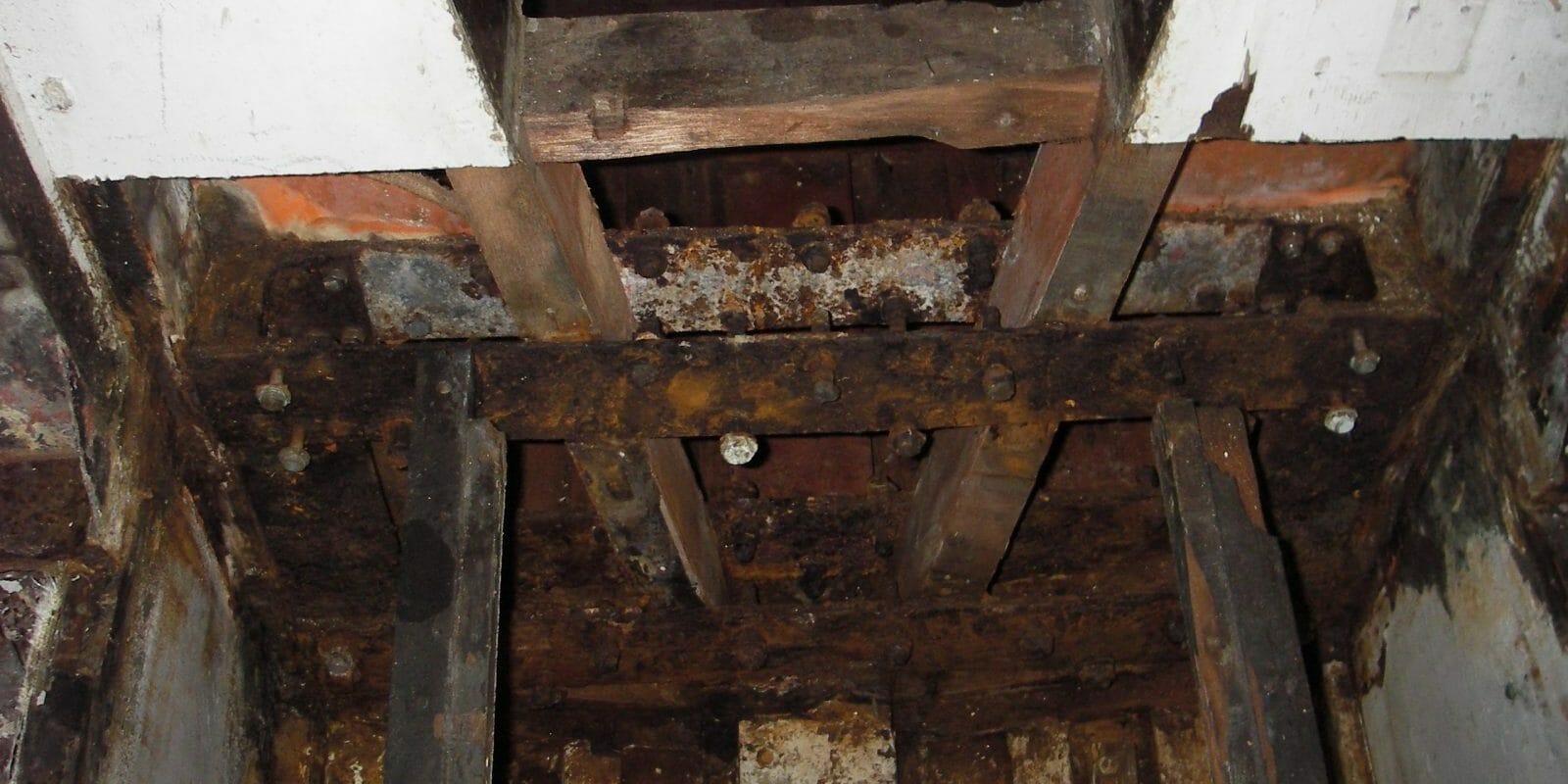
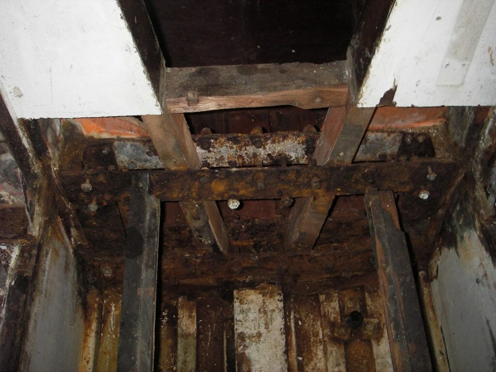
On each keel arrangement, there was a pivot bolt and two additional clamping bolts. All were mounted on a solid frame between the two inboard sides of the keel box. The frame and bolts were un-galvanised mild steel and in no way did they resemble the three dimensional brackets that subsequent production boats enjoyed.
The keels had to come out, as did the partially rotten keel box timbers. I can honestly say that I read up about and then employed all the practical advice available, but to no avail. I was loth to create too much collateral damage. In the end, I had to employ a long reach mechanical reciprocating saw from underneath the boat, to cut through both sides of each pivot bolt. That was the keels out; they went off to be shot blasted and epoxy coated. Whilst they were away I took the opportunity of having the keel pivot holes re-bushed in stainless steel as the holes had become very worn.
With the keels out of the way, removing the remaining metal work using brut(ish) force and an angle grinder on the corroded screws, nuts and bolts, was in comparison, quite straightforward. The various timber bulkheads and keel boxes came out at the same time – they were largely rotten.
Then came one of the big decisions; do I replace like with like, or do I change the arrangement? I decided the latter because that’s what the chaps at Fairey Marine did all those years ago. But because A1 is the prototype, the keels have quite different scantlings, so the existing drawings that are available for subsequent production boats, do not work for A1.
I made very careful measurements and then drew up my own version of the clamping arrangements. The drawings were taken along to a local engineering firm who then manufactured the support brackets in stainless steel. Stainless bolts and clamping plates were also made. Much later in the project, these were bolted in place to the new keel box and bulkhead timbers and the keels lifted back in position. Thankfully, it all went smoothly!
A couple of other changes were necessary as well. The transverse bulkhead that sits beneath the fore-cabin companion way, along with the inboard keel box wooden plate, supports the weight of the keel support brackets and indeed the keels. Originally on A1 this transverse bulkhead had been hollow, encapsulating the various bits of the metal framework. In creating the new brackets, I replaced the ‘hollow’ bulkhead with two thicknesses of 25 mm thick marine ply. As this bulkhead also supports the mast step, the downwards thrust of the mast had to be transmitted down to the bulkhead and the keelson. This meant a modification to the upright timbers.
-
A1 3.1 Looking forward from the engine space, through the main transverse bulkhead (note rotten step), into the for’d cabin – the badly rusted and corroded metalwork for the old keel support brackets revealed from where it was hidden in the ‘hollow’ bulkhe
-
A1 3.2 Inside for’d cabin – old mild steel keel support bracket
-
A1 3.3 Inside the boat on the port side – holes prepared in the transverse bulkhead and the inboard keel bow panel – to accept the three dimensional stainless steel keel support bracket
-
3.5 A1’s keel hoists operate to the same principles as the production Atalantas, but with cables instead of solid stirrups.
-
A1 3.6 New keel plates and clamping bolts in stainless to Mike’s own design. These are more inline with production boats than the originals.
-
A1 3.7 Port side keel bolts and clamps


Wow Mike, respect. The work that I had to do on the keel assembly pales in comparison to what you achieved.