
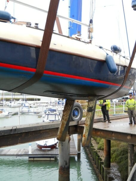
A89 with her keels fully lowered
Retractable keels
The Atalanta has a canoe body which has no form of fixed keel what so ever. All of the ballast is contained in lifting keels. Two of them. The unusual feature is that these keels are side by side.They pivot like a centreboard so that they can each fit inside a separate centreboard case. The ballast is split into two equal portions, so that each keel, weighing 400kg, can easily be hoisted into its casing using a built in winch mechanism. Draft with keels lowered is 5 foot 9 inches, and with keels raised 18 inches.
How does it all work?
The keel system is quite unlike the typical lifting keel or centre board found in dinghies or cruising yachts.
Typical centre-plates are supported on a bolt or pin passing through the sides of a casing, and when lowered press against the wooden sides of the casing. These plates are usually free to rise, only held down by gravity and the sideways pressure of the boat sailing to windward. This arrangement transfers all of the forces created when sailing into the wooden centreboard case.
The Atalanta is different.
By the way whenever you see “Atalanta” in this document you can assume that it also means Titania and Fulmar, unless the text specifically states otherwise.In the Atalanta each keel is supported by, and held firmly against, a metal structural support arrangement. The photo below shows the metalwork, looking towards the stern, assembled in a boat:
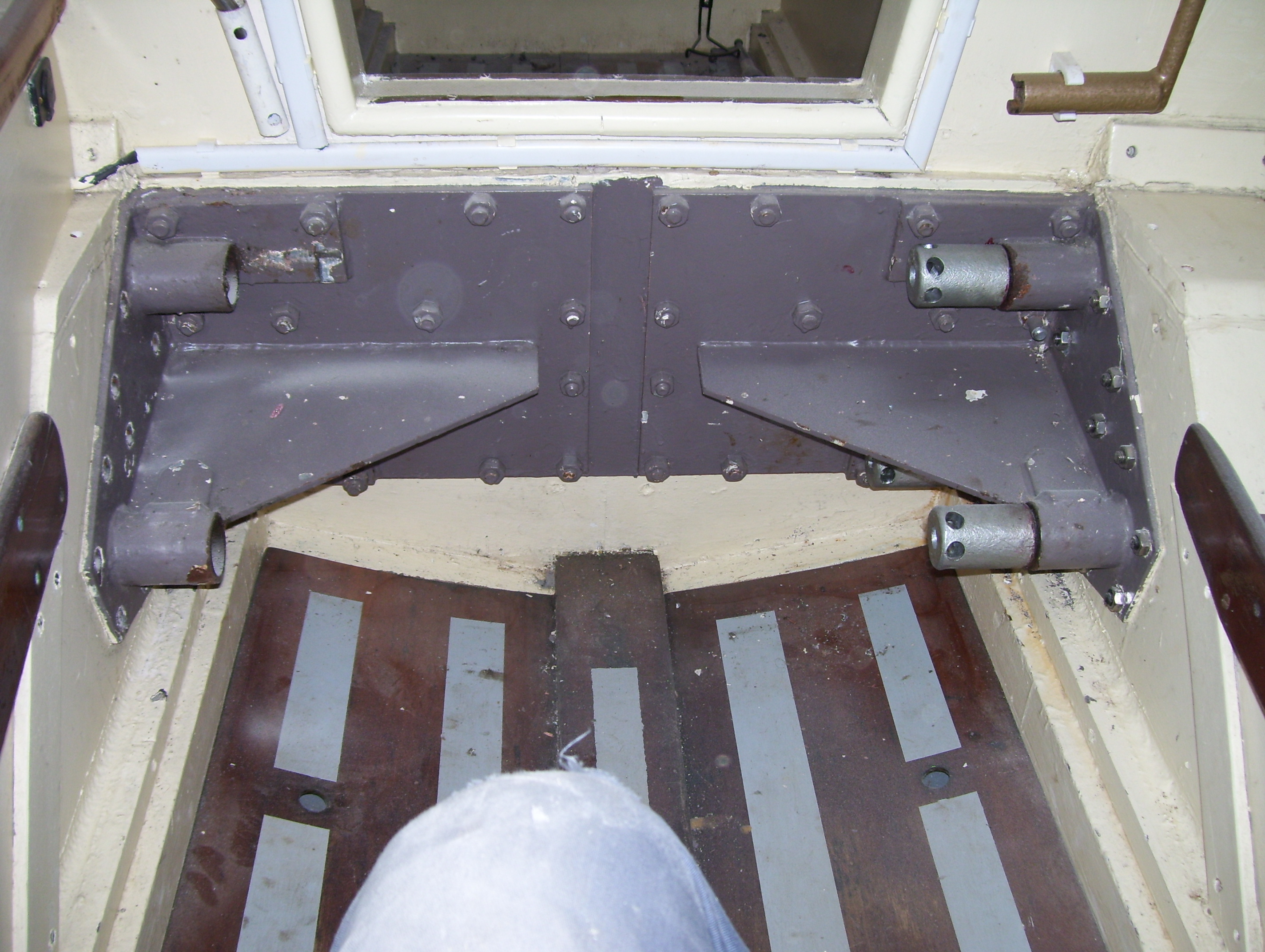
The main bulkhead from forward showing the keel mounting structure
The photo below shows it from the aft side of the main bulkhead looking forward:
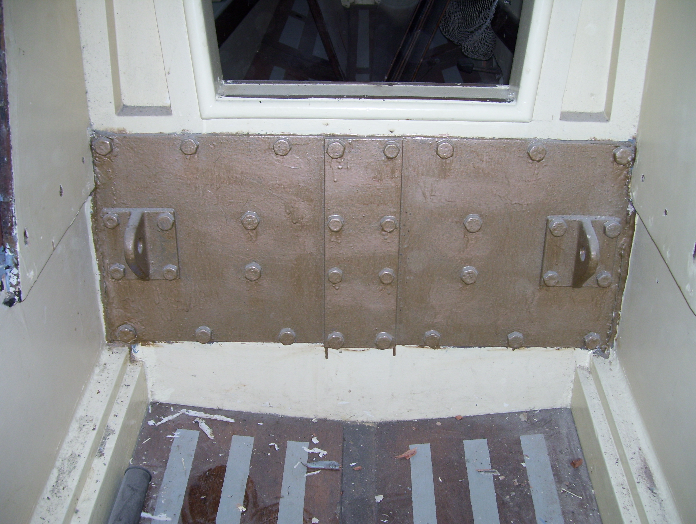
The main bulkhead from aft showing the keel mounting structure
This framework passes the stresses from the keels directly through to the main bulkhead, and then distributes it into the structure of the boat.
The following photo shows one of these supports:
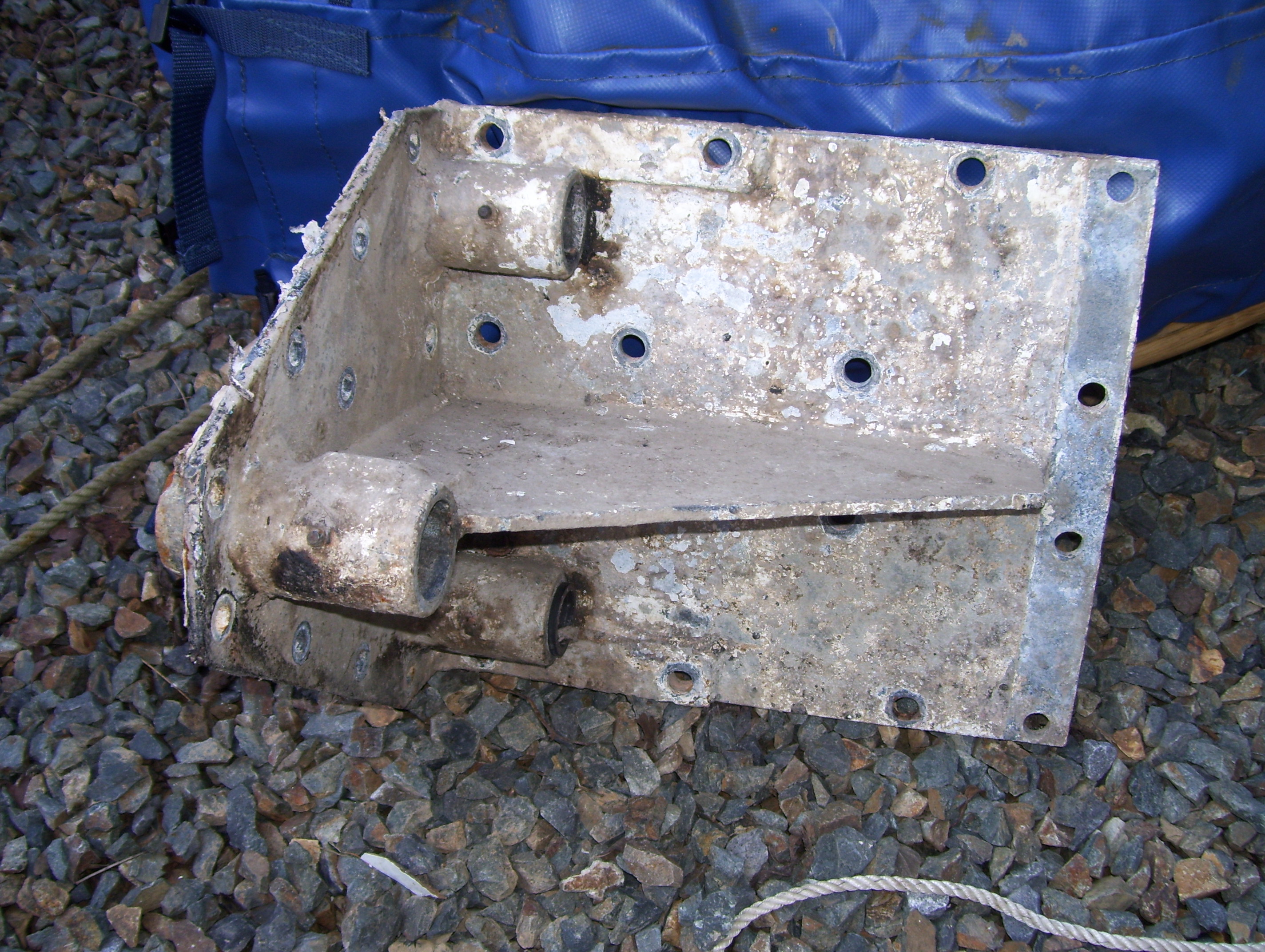
The support structure for the starboard keel of an Atalanta. Bolts pass through the three tubes and clamp the keel to it.
The three tubes pass through the keel box (we Atalanta owners refer to our “centreboard cases” as “keel boxes” – don’t ask me why – we just do!). The side with the tubes in it is bolted to the inner side of the keel box, and the other side is bolted to the front of the main bulkhead – the bit that you have to keep climbing over. Most of our boats have a thin plate within the keelbox which takes the heads of the machine screws which hold the main structure to the keel box inner side.
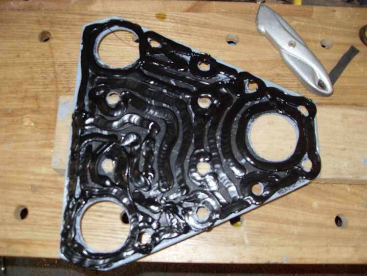
Plate which holds the triangular support structure to the keelbox side
This photo shows the thin plate with the three holes for the tubes to pass through and countersunk holes for the bolts which pass through the side of the keel box.
The ring bulkhead
Look at the first two photos again. That part or the support bracket which is bolted to the main bulkhead is bolted through the bulkhead to a thick metal plate on the aft side of the bulkhead. This plate also connects the supports for the port and starboard keels together. This metalwork actually transmits the forces from the keels directly into the main bulkhead. The tubes which pass through the keel box side are long enough to clear the keelbox side and the thin plate, and press directly onto the keel system in the keelbox. There is no strain applied directly onto the wooden keel box from the keel.

Pressure plates
On each side of the keel there is a pressure plate, and the three keel bolts pass through each of these plates, into the tubes in the support structure. A nut fits on the end of each bolt – and these nuts are tightened when the keel is in the desired position to firmly clamp the keel in position. Only one of these bolts passes through the keel – the lowest aft bolt. This is the one that the keel pivots on. The other bolts pass, one above the keel and one in front of the keel. The pressure plates enable the clamping force from all three bolts to hold the keel rigid. So – the keel is unusual in that it does not move when under way but it is held firmly, side to side, and fore and aft –unless you loosen the nuts! It is also unusual in that the forces are not transmitted to the wooden centre board case – but bypass the wooden structure and are applied directly to the main bulkhead.
Keel raising
The keel is raised and lowered by turning a removable handle which fits into a keel lifting mechanism located on the aft side of the main bulkhead, one either side of the passageway through the bulkhead.
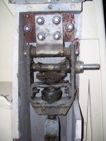
The bevel geared keel hoisting winch fitted on an Atalanta
This handle turns a horizontal shaft, and through spur gears rotates a threaded rod which hangs vertically down into the keel box. A nut is threaded onto this shaft and runs up or down the rod as the handle is turned. An inverted “U” shaped stirrup rides on top of this nut, and its lower ends connect to a pin which passes through a lug on the keel itself.
Kicking Up
The idea is that normally the top of the stirrup sits on top of the nut, but if the keel hits something, and is forced back into the keelbox, then the stirrup rises up away from the nut – allowing the keel to rise without damaging the lifting mechanism. When the obstruction is removed (you have passed over the rock?) then the stirrup drops back down into contact with the nut – probably with a thump. The lifting mechanism is fixed to the main bulkhead at shoulder height.
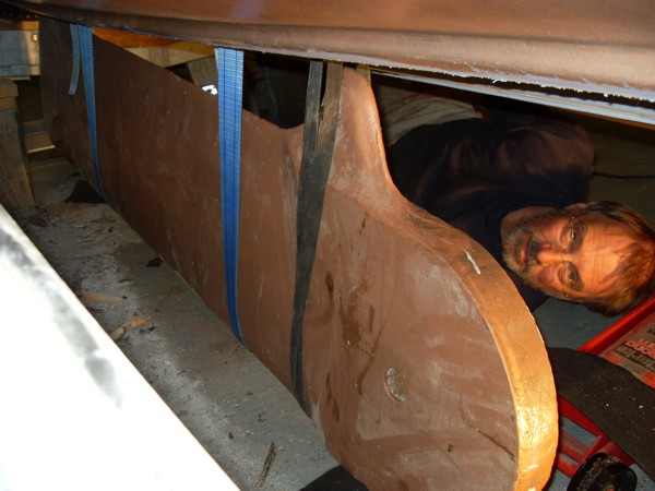
The repainted keel is being lifted back into place in the boat