 Ok, so I have actually been doing something.
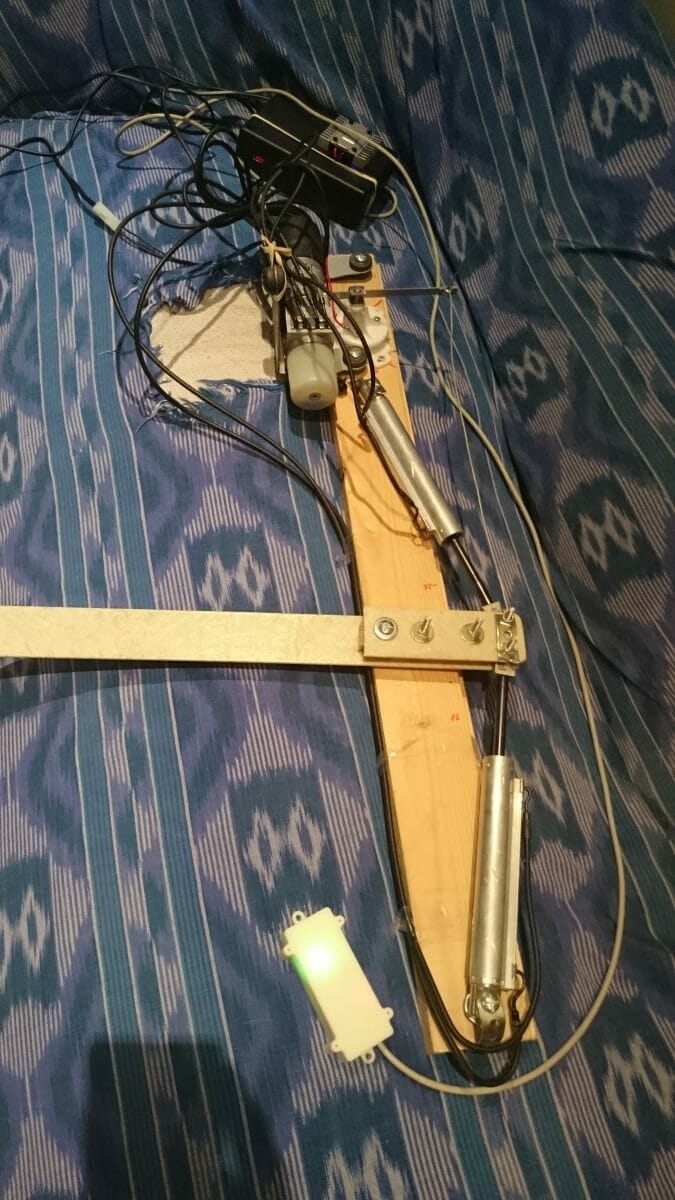
I can’t just turn up to the boat and hope it works so I have created a test set up. It is made from an old batten. The pivot point is the left most bolt, I left the length to the left of that to see the speed of movement I would expect from the actual rudder.
From the top; The black box you can see at the top is the project box that contains the arduino and freeboard circuit boards as well as the bluetooth module. You can just make out a red dot which is a 4 digit 7 segment display which I initially used to indicate direction. The metal bit on the top is the motor controller heat sync.
Then coming down you can see the motor and to the right of that the rudder position sensor. There is a bit of fencing wire between that and the end of the ’tiller’.
This is now stand alone and powered by a 12volt car battery I have under my desk.
The cool thing is that I can set the rudder position and it moves to that position.
The difficulties I have between now and a usable system is the quality of the compass which I hope just needs calibrating properly. Unfortunately I have an iron girder near my desk 😉
The other thing that I see as a risky area is the control loop for that includes the compass. I can use the COG from a GPS I have, this de-risks the use of the compass. But it is the tuning of the feedback loop might phase with the motion of the boat if it isn’t tuned properly.
I am using a basic Phase, Integral and Derivitive (PID) loop which I might have to tune based on wave size. I am not sure…
The thing that has made this quite cool is that I have managed to use a bluetooth low energy link to my mobile to do the configuration. The only problem is that I spend too much time making it ‘pretty’ and not enough making it functional. I am learning a lot so sometimes it is more ‘look what I can do’ as opposed to what I need to do.

I hope nobody minds as I have lifted the background image from the Atalanta brochure. The centre of the compass is also an edit from the line drawing.
The idea is that the outer compass is driven by the phones compass so it always points north. The image for the boat rotates within that pointing to its compass bearing. So the image should be aligned with the boat.
The bottom of the screen is, at the moment, three swappable panels for bearing, rudder and GPS speed (obviously, that is important). In the one pictured the smaller number is an editable field which gives the rudder position wanted. The big one is the actual position. I edit the little one and the big one aims at that number. For the rudder it works.
The trick I want to pull off before September is to have the steer by compass bit working. But I don’t have that many weekends left.
But it is looking all very plausible at the moment..