Forum Replies Created
- AuthorReplies
 Trevor ThompsonParticipant
Just occured to me that you might need to be careful using another boat as a patern. They might not be the same. Try to find one with a number close to Fairey Mary to minimise the risk of there being differences.
Also you might want to think about a Bimini. Not as easy to do on an Atalanta as on a Titania because you have a bigger cockpit. The main problem will be keeping it low enough to clear the boom. I raised the boom on my boat (to reduce the risk to children, who are now adults), but it does make it easier to add the Bimini.
 Trevor ThompsonParticipant
Havn’t got room to fit the tug in. However if it is just a photo to add – then yes
Trevor
Trevor ThompsonParticipantYes they are supposed to plane. I spoke to Simon West (A5) who was describing how they had A5 planing, when we were last at Beale Park.
More surprised to hear that a Fairey Fisherman planes, are you sure about that? The Fisherman is a lifeboat hull. Designed as something to do with the mould after fairey failed to get the contract to build ships lifeboats.
Trevor ThompsonParticipantI think you are correct about the weight. Peter Cranes boat Eirena is very light and sails very swiftly. I have been experimenting with sailing to windward in light airs with one keel fully raised (it was stuck up for a couple of days) and she was certainly swifter to windward like that. I also know that I gain almost a knot motoring in a calm when I fully raise both keels.
Not sure I would want to reduce the weight of the keels though – they have a low ballast ratio as it is. Of course it could be carbon fible keels with lead in the bottom! that would increase the righting moment without changing anything else.
I suppose my final comment would be that they are already fairly fast OFFSHORE. As in when there is wind F4 and above they keep up with boats which are significantly bigger. Perer Crane and I sailed from Falmouth to Penzance in winds of F4 to F6 from the SW. When on the moorings outside Penzance harbour we recieved comments from the crews of the 35 ft boats which also made that passage on the same tide along the lines of “those boats are fast, we couldnt catch you!”
To me it is important to have a boat which feels secure at sea, so while it might not be as fast as boats intended for racing, it inspires confidence in me. I have taken it out of shelter in some pretty strong winds! So I dont actually feel that the performance needs improving!
Trevor ThompsonParticipantIt is a good ides to have a cover like this for the med. I have one which is very similar to that you are describing. In my case it zips onto the front and back of the Bimini, in three sections. One aft, one to the mast and one in front of the mast.
Best wishes
Trevor
Trevor ThompsonParticipantJim
Thanks for the article.
I dont want to put the email adrress on the website for everyone to read. My contact details including email are in the yearbook.
Trevor
Trevor ThompsonParticipantThe drawing calls for Mahogany, but I am sure that you can substitute another hardwood, which might be easier to get locally. The sealing board is shown on drawing C24824. It should be 4 ft 2 5/8 inches long.
Trevor ThompsonParticipantHi. Sorry not to reply earlier – been away sailing.
I have used the same system which is described in this post, namely armourguard and copper coat fromn reactive resins. It has now been on 2 years. Basically I am very pleased with it.
The one thing I would state about the copper coat is that it is not totally imune from fouling. However we have had a very bad year for fouling this year and all I have are barnacles underneath, between the keels, and along the keel itself. The unprotected prop and shaft was covered as well. Very little “weed” as such. So I suppose the point is that I find I have to dry out half way through each year to scrub it all off.
I am however convinced that it would be significantly WORSE if I used conventional antifouling.
As far as repairing the coating is concerned it is easy. Just abraid and degrease the affected area and recoat. I have found the armourgaurd very good – it does stick to steel and galvanising well. I have even used it on alloy and it stays on that as well.
Trevor ThompsonParticipantMurray please could we have information on how to make it!
Trevor ThompsonParticipantSeems a lot of money to coat such a small area! I think that there are a number of alternatives to this.
Firstly I used the best I could find on Calista’s transom after the accident. I used a special epiphanes 2 component varnish which can be overcoated after (I seem to remember) 6 hours, to build up 6 coats quickly, and then used 2 coats of ordinary epiphanes varnish to add UV protection to the finish. The special 2 pack was £75 per litre – and I have loads left over. The ordinary stuff was in the order of £25 a litre. I am sure I must have described it in the blog at the time.
I have also experimented with the cheap “yacht varnish” which you buy from DIY shops. Here in Wales the cheap supplier is Wilkinsons – I suspect they are a nationwide chain. It is about £12 per 3/4 litre. I would use a coat of boiled lineseen oil brushed on liberally onto bare wood. Apply 4 coats of varnish on top starting after 24 hours. I recon that gives a self healing effect in case the varnish gets scratched. I have used that succesfully for many years.
Whatever system you use I think that it is important to give the varnishwork a quick rub down each year and add a fresh top coat to renew the UV protection. Keeping the varnishwork out of the weather in the winter, and adding a fresh coat each year really does make it easy to keep varnishwork looking good with the minimum of effort.
I have not had to strip anything (mast, boom, toerails, coachroof, cockpit) back to bare wood in the last 10 years.
Trevor ThompsonParticipantChris
Word for preference. Photos seperately as jpeg files rather than incorporated into the text please.
Otherwise you have a free hand!
Trevor
Trevor ThompsonParticipantThe black stains are caused by mild steel staples which were used during manufacture to hold the second layer of veneer while the third layer was added. As a result these marks are usually near the centre line or at the joint between components. You will be able to partly remove the staining but it will always come back unless the staples are removed from the lower layer. However there may not be much of them left by now!
The oxalic acid is the correct way of minimising the staining. I have used bleach in the past. Either way it needs washing well and drying afterwards. Otherwise just live with the staining – it is part of the character of the boat!
As far as finishing afterwards. I would use a clear varnish. My coachroof is coated in traditional varnish. Six coats, and an extra coat every year. It is much easier to renew the surface yearly – to retain the UV resistance – than to let it deteriorate and have to strip it back again. Incidantally try not to sand too much off – or you will go through to the middle layer of veneer. You certainly dont want to have to strip it back too often.
I have used boiled liniseed oil as a primer coat in the past. Then overcoat after a few days with normal varnish.
If you want to use epoxy. You could roll on two or three layers of epoxy to soak into the wood before applying 2 component epoxy on top. You still need lots of coats (6?).
I have been reluctant to use a glass cloth with the epoxy because I have had trouble getting all of the air bubles out from under the glass cloth. Others have used it with varying amounts of sucess.
Trevor ThompsonParticipantDinah is now back at home and if you want a copy of the keel manual we aught to be able to organise it. It is really a printed booklet – but it is also available as a PDF – however it might be a bit big to send as an attachment. We could try if you want. Consult the Hon Sec about payment, and we can take it from there.
Trevor ThompsonParticipantJust for clarification – there was an error in the information I passed to John, and which he posted in this thread. The main chocks do go under the two bulkheads at each end of the cockpit. One does not go under the diagonal bulkhead.
I was confused for a while by the differences between Titanias and Atalantas. I have the chocks in a different place on my Titania.
Trevor ThompsonParticipantThe coachroof and the deck of an Atalanta are made made from three layers of 2.5mm thick agba veneer, each layer layed at 90 degrees to the one below. So it isnt plywood, as such.
To make a proper repair is actually quite easy, when you go about it in the proper way which is described in one of the original Fairey marine drawings. Lots of people seem to want to find a shortcut – but perhaps it is easiest if I describe how to do it properly.
Firstly I would start on the inside. Look at the actual hole. That is the size of the patch you will need to fit into the MIDDLE layer. It is probably easiest if you sand or scrape the paint off around the hole so that you can see which way the grain is running in the lowest (inside) veneer. Now draw a pencil line in a diamond shape about 1/2″ to 1″ bigger all round, making the diamond shape longer in the direction that the grane is going. Hold a metal rule against the line and cut along it with a stanley knife. You MUST use a new blade. Press gently at first and go over the line pressing a bit harder each time until the blade has cut down about 2mm. Now use a sharp chissel to carefully cut out the diamond. You will see the glue line as you cut it away so you will now when to stop cutting deeper. You can cut around the actual hole to make a square or regular shape for the hole in the middle layer.
Cut a piece of paper large enough to go over the diamond shaped hole and press it firmly into the edges, taking care to make sure it does not move. You can draw around the edges with a pencil, but I just crease the paper into the edge of the cutout pressing firmly with my nail.
Cut out the diamond shape from the paper and try it in the hole – it should be a good fit with no gaps. When you are satisfied with the pattern, hold it onto a piece of veneer, and using a metal rule cut it out in the same way as I described cutting the deck. The resulting diamond shaped patch should be a good fit into the hole.
A second similar piece of veneer can be cut out slightly smaller to use to make the patch for the middle layer. Hold it in place temporarily with a couple of staples from the inside, while you draw around it from the outside to get the shape of the hole in the middle layer. Cut that patch out. You can now fit these two patches permanently. Most of us use West epoxy, for this type of repair. It is less temperamental than most epoxy systems. Whatever glue you use it does need to be waterproof and structural. If you use an epoxy (which I recommend) you will need to mix filler powder into the mixed resin and hardener, until it is the consistancy of peanut butter. Fit the inner layer and staple it in place, then fit the middle layer patch from outside.
You can leave the epoxy to set and deal with the outer layer the next day.
How far should you cut back the outer layer?
If you want a professional repair in a varnished surface you have to cut the outer veneer back along the grain each way until you meet an obstruction. Also it has to be as wide as the original veneer. The idea is to leave the finished surface with no extra joins.
In practice if you accept that the edges of the parch will be visible or it the surface is painted than cut out a patch just like that in the inner layer, using the same techniques, and glue it in place.
The repairs can be sanded after 24 hours, and you should hardly be able to see the edges.
If you let me know how big the hole is (small I presume?) I can bring some agba veneer to Doggets for you.
For reference Robbins Timber of Bristol stock Agba veneer.
Dont worry about UV resistance which will be provided by the paint or varnish you apply over the patch.
Trevor ThompsonParticipantSorry to be a bit late to respond to this – I have been busy with the annual bulletin.
Can we confirm that we are talking about a blown air deisel heater such as an eberspacher or a webasto unit? I presume it isnt a vertically mounted unit such as that illustrated in Timothy’s photos? It makes a big difference.
Calista has an Eberspacher Autronic D2 mounted in the engine compartment. There is plenty of room on the starboard side aft to fit this type of heater. Atalanta engine spaces are even longer than Calista’s by the way. The inlet combustion air it taken from the engine compartment. The exhaust passes through the bulkhead into the aft cabin footwell over the top of the footwell and out of the side of the boat just below the gunwhale. The exhause is important so some detail:
It is constructed from the manufacturers stainless exhaust tube (important that you use propriatory exhaust tube intended for this type of heater). I must emphasise that the exhaust is REALLY well insulated using multiple layers of glass fibre tape intended to insulate rally car exhausts. It has an outer layer of corrugated alloy tubing to protect humans from the glass fibres. In operation it is cool enough to HOLD the outer alloy layer when the heater has been working at full power however long it has been on. The clamps on each end of the exhaust need to be checked for tightness periodically – I have known then fall off after an approved installer has finished servising a unit on a commercial vessel.
The inlet heater air is taken from the port footwell, and the heater output is ducted to the aft cabin, main cabin and forward cabin, as well as the oilskin locker. (Titanias are slightly different to Atalantas). All of the heater ducting is insulated. This model of heater has its thermostat in the heater itself. So it needs to take air from the cabin, not cold air from outside, if it is to know when to turn the heat down as the cabin heats up.
The control unit for the heater is mounted on the bulkhead inside the cabin. It has fault code reading facilities to help to maintain the heater.
Incidentally, I have found that it shuts itself down to a low output mode quite quickly, and takes less than an amp in this mode. So I have used it on long winter evenings while cruising out of season away from shore power. I dont tend to leave it on overnight – although I am sure I could.
Final comment: I chose this type of heater deliberately because I wanted to heat all areas of the boat including the aft cabin, and I wanted it to use diesel fuel. I dont think any other type would have done what I wanted.
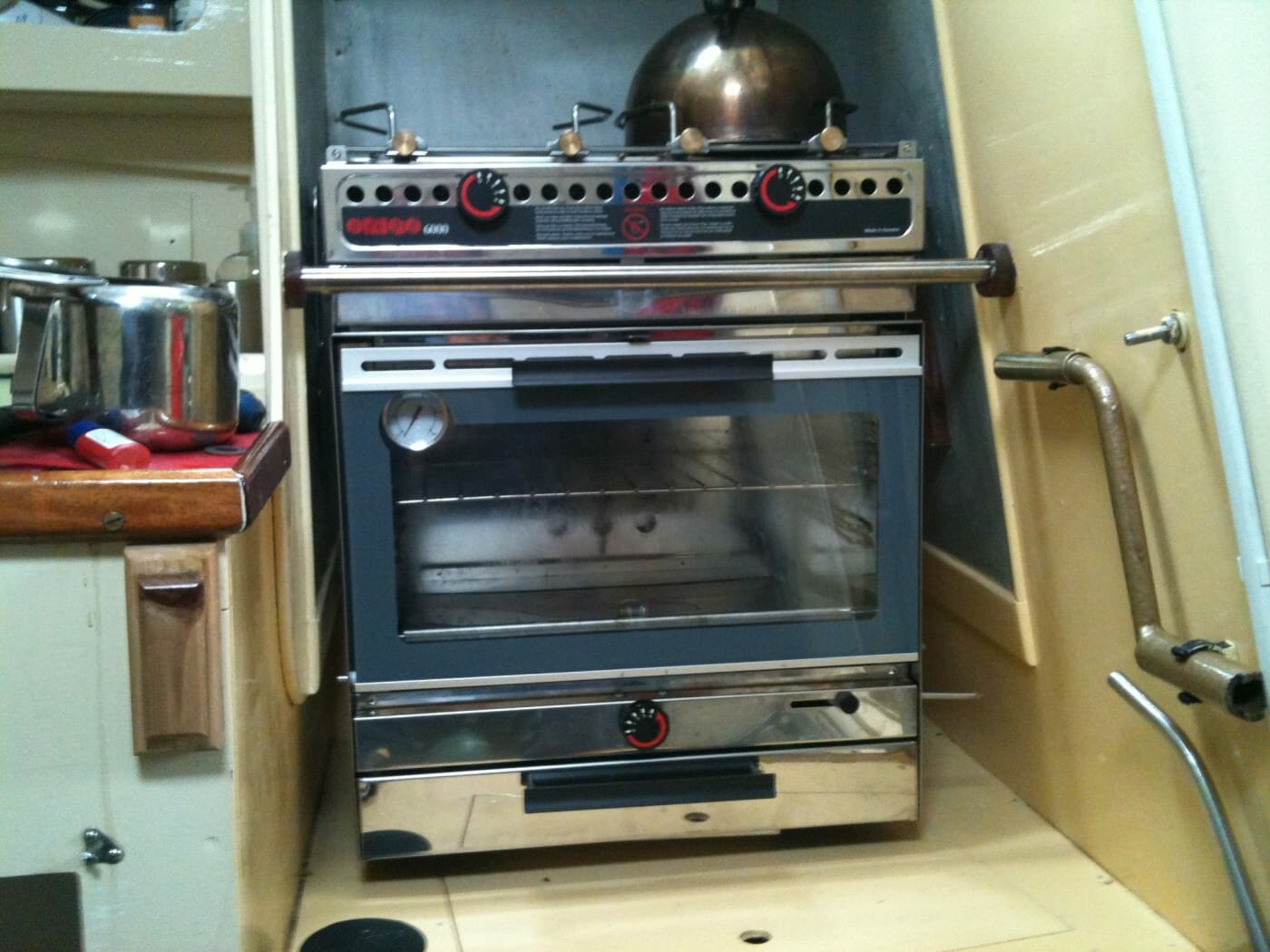
Trevor ThompsonParticipantWell I tried to get the stainless wire etc but it was going to cost a fortune. So I thought again and decided that I would wekd it with mild steel wire. I suspect that it will not corrode swiftly since there will be some migration of material between the stainless components and the small amount of weld I will create. Anyway it is repaired. Rivetted the burner carrier back into position, took it to Calista and assembled it in situ.
Photo:

It fits into the space perfectly. I know the crash bar is not level – I did level it after looking at this photo. It just swings enough. You can see the rod sticking out on the right hand side which is the lock to stop it swinging. I measured up for a block which I have made and will fit tomorrow.
So then I had to try it out! Having filled the meths container it lit fairly readily although it did go out at first. Anyway after relighting it I managed to get the temperature in the oven up to 200 degrees Celsius.
Photo:

Pretty poor phot I know. But it does show that I got it to 200 C!
Dinah tells me that is hot enough to bake bread. So that is OK then. Might try bread tomorrow.
Trevor
Trevor ThompsonParticipantWell I have worked it out! So since I posed the question I had better tell you the answer!
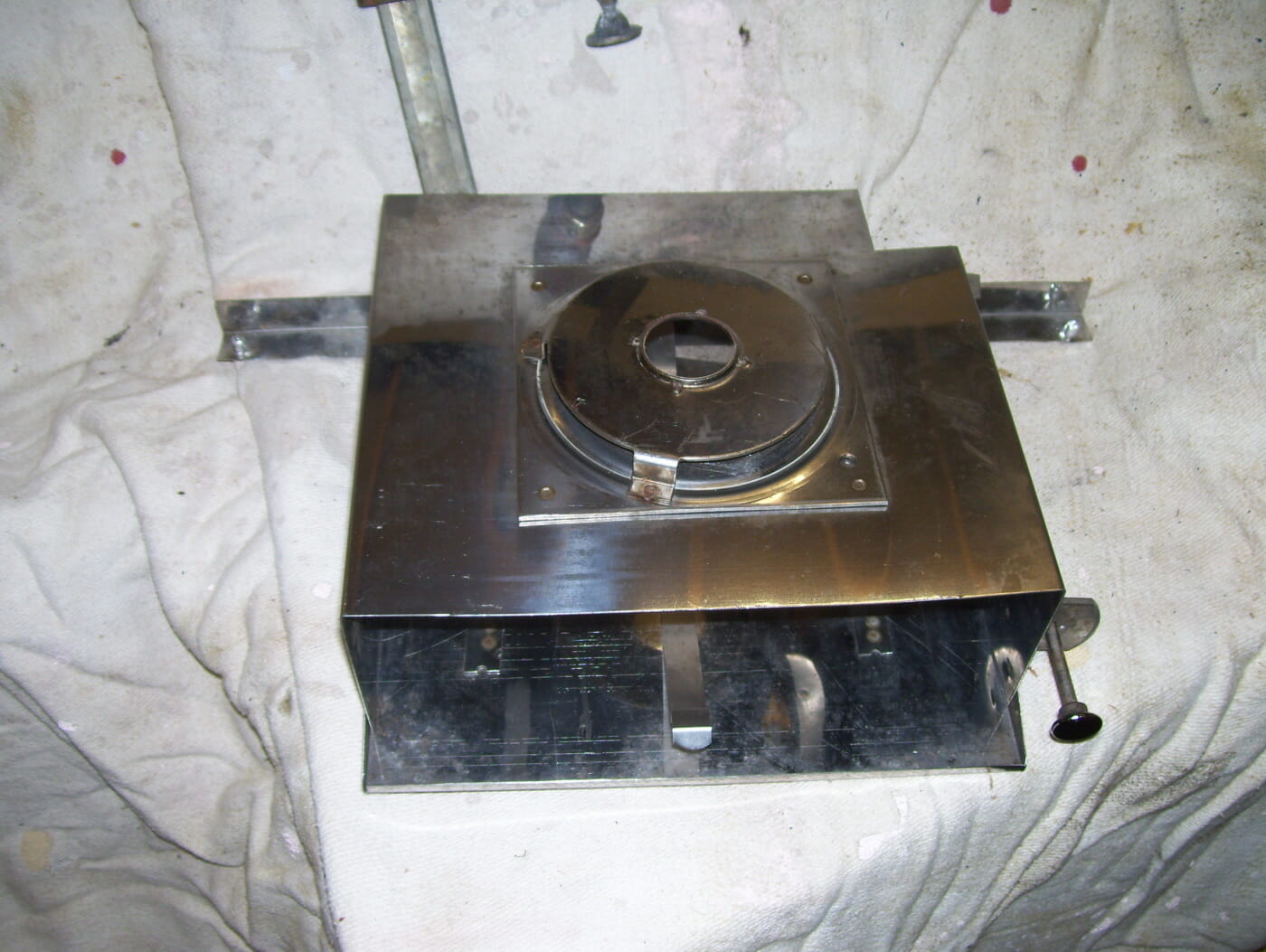
I have found a photo on the internet of one installed in a boat – in the USA I think. It satisfied me that there was no tray or floor underneath the oven. So I suspected something had come apart that should not have. Anyway I took the front strip which contains the control dial off. It was held on by 4 pop rivets so it was easy to drill them out. This is the result:

The tube in the centre of the picture is the burner nozzle.
Now when you look at the carrier unit:
When you look closely at the hole in the centre of this picture you can see 4 dimples, just on the outside of the holes upturned flange. They are actually the remains of spot welds. When you turn over the component in the last picture you can see similar marks. Originally I thought they were dimples to provide a gap for air to get into the burner. Having confirmed that there is no missing floor, I thought again and looked more carefully.
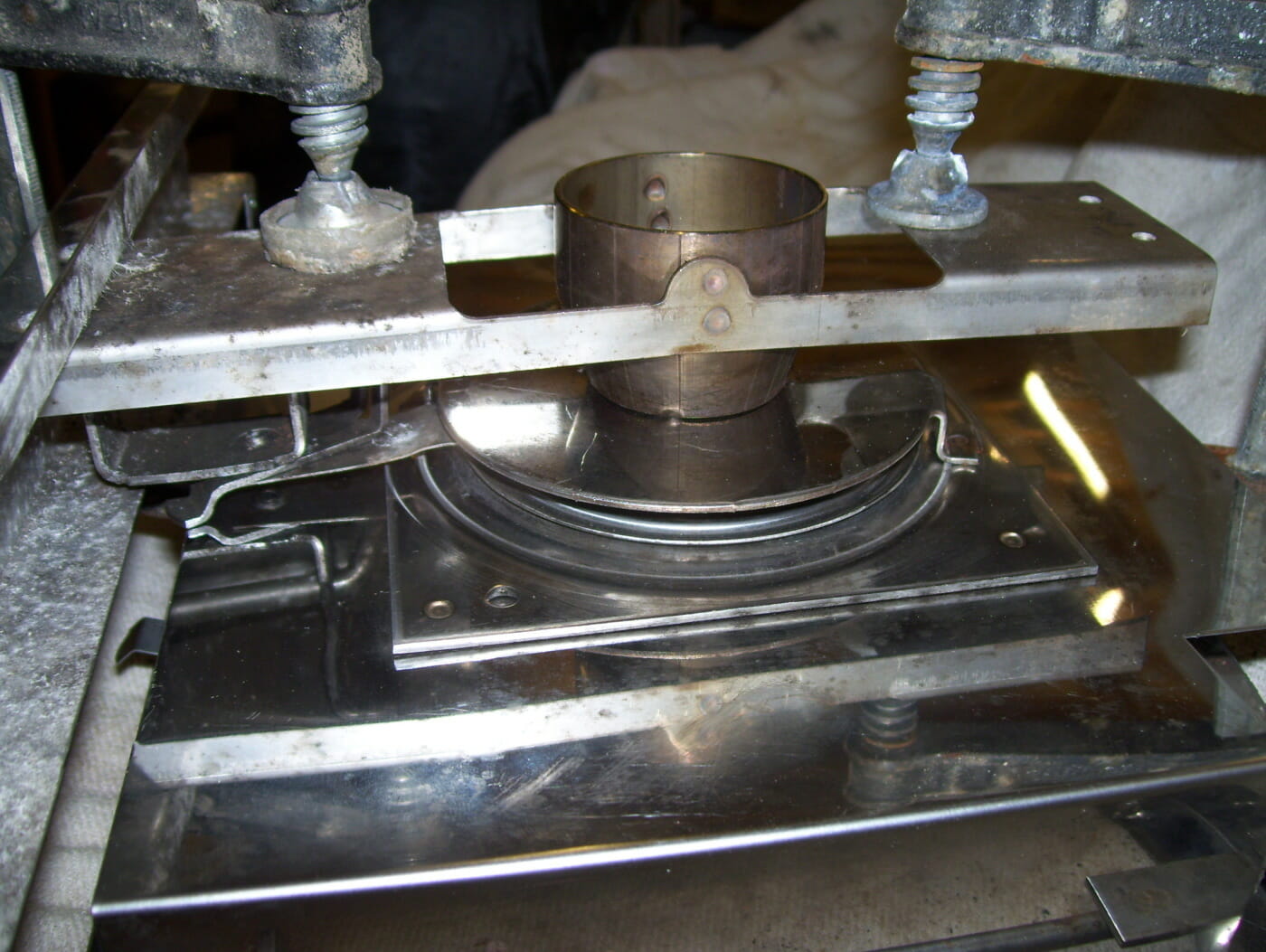
So this is the burner unit held together for welding:
So now I need to buy some stainless welding wire and weld the two parts back together. Then it will just remain to rivet the complete unit back into position.
So problem solved!!!!
In case you are curious I did get a partial refund on the purchase price to reflect the fact that it was not in the “excellent as new condition” that was claimed. I didnt want a total refund (which I was offered) and to give it back – I knew I would be able to repair it when I had worked out what was wrong with it.
11/09/2013 at 18:56 in reply to: Request for drawings that the association does not have access to. #10264Trevor ThompsonParticipantIt would be brilliant if you did have it.
Scanned copy would be even better!
Thanks Trevor
Sorry for delay been away at sea! (Not on Calista)
Trevor ThompsonParticipantCalista has a manufacturers plate made from brass. It just states the makers name and address, with no details of the model or the number. Does anyone else have anything different?
Trevor ThompsonParticipantTim
The skeg on Calista (which was damaged in the accident) was fitted by me about 5 years ago (probably nearer 8) and I used NO metal fixings in it. The skeg was made just like the new replacement from timber strips epoxied together and epoxied on to the hull and transom. You should be able to see from the photos that the glue lines all held firm. The part of the skeg which passes up the transom was ripped from the rest of the skeg – and the skeg itself was ripped from the hull – parting through the middle of the sandkeel. I dont think metal fixings “reinforcing” it would have helped – the forces were so great something had to give. At least having no metal fixings minimised the damage to the hull and transom.
So what I am getting at is that I have not used any metal fixings in the replacement either – I am sort of suggesting you might not need to use all of those coach bolts criss crossing accross the skeg.
Trevor ThompsonParticipantDominic
I cant get it done via that trainee engineer, he is now in the surface fleet, and working on a ship based in Portsmouth. I really want a proper invoice for the insurance as well. So I am going to try the wooden stock out. It does take a standard blade by the way. It will need a new bush for the centre to go with a new nut and bolt in stainless. It will be good to get away from that horrible alloy nut and bolt – a different bolt is specified on the drawing for the wooden stock.
Trevor
Dominic Dobson said:
Sorry to hear of the accident you dont seem to have a lot of luck with other drivers! just a couple of thoughts have you tried contacting Martin Bennet re a welded stock he always seems to be able to fabricate stuff, or how about finding a trainee marine engineer to do one as a project Im sure the grey funnel line will have some spare alloy knocking about around the Clyde. The wooden stock seems like a good idea does it hold a standard alloy blade? At least a wooden stock will be quick getting you back on the water even if its as an interim measure whilst you source some one to fabricate one in alloy.
Dom
Trevor ThompsonParticipantSimon
I would normally have said axactly the same. (probably have gone on a bit on the topic). However when I take things to pieces I realise that Calista has had a stainless bottom pintle burried in the skeg for many years. It was there when I bought her, and I put it into the new skeg I made some 6 or 7 years ago. I would have reused it again – there was no sign of corrosion at all, but it was badly bent. I have sort of straitened it – but am worried about the stress it has been subjected to. I dont want it to fail at sea in bad weather!
I cant help using stainless on the bottom gudgeon attached to the rudder stock, so I might as well have a matching fitting made up to go into the skeg. That also fits in with what you said about different materials. All of the fittings on the rudder will be stainless, except for the rudder blade itself. That will be totaly isolated from the stock and the fittings. I will even insulate where they attach to the uphaul and downhaul.
I have actually ordered the three fittings!
Trevor
Simon Garratt said:Trevor,
Personally, I would be really cautious about using stainless under water or any where without contact with oxygen (ie buried in wood) especially if galvanic action comes into play – as I am sure you are aware Stainless & aluminium are poles apart galvanic wise. I have had personal experience (on a previous boat) to this effect – stainless looks ok on the outside but in the wrong circumstances crystallises & weakens internally. This is the main reason why I went for aluminium again on my pintle (though as with stainless you need to consider the grade you need for the job in hand). It’s also why I have taken steps to isolate the stainless from aluminium – at least a visual inspection of aluminium or steel etc tells you when its time to get a new one.
Regards,
Simon
Trevor ThompsonParticipantMurray
That is for fabricated ones made from stainless. There are seperate drawings for the fabricated ones.
murray reid said:Ouch! Is that having the pintles and gudgeon milled out of solid stainless? Why not get some fabricated ones welded up?
murray
Trevor ThompsonParticipantMurray
The drawings specify 18mm ply. I have priced a 1/4 sheet of the best ply at £65, which seems OK. So far I have only had one quote for the pintles on the rudder (detatched stainless versions of the alloy ones) and a new gudgeon for the skeg. The price is £900 plus VAT!
Trevor ThompsonParticipantSimon
I need to get new rudder fittings made for Calista. The rudder stock was bent like a banana in a road accident. Can you provide me with contact details for congleton engineering please?
Thanks Trevor
Trevor ThompsonParticipantNothing to add about taking it apart! Just adding information on how I repaired Calistas bearing.
I bored out the outer tube, and cleaned the shaft up in the lathe. I then made up a phospor bronze bush to press into the tube in the lathe, and finished off the inner diameter of the bush to be a good sliding fit with the shaft. I drilled through the grease hole and made a slot along the bush to distribute the grease along the shaft.
Not that I think you all have lathes in your garrages, but it can be repeated by taking it to an engineering workshop.
Trevor ThompsonParticipantCalista has 6mm chain – and has had this size from new. The original chain was 120 ft long. Whatever size of chain / warp that you carry recovering it in strong winds or tides can be really difficult – so I am strongly in favour of having an anchor winch / windlass. Because I fitted a winch I had to buy calibrated chain and bought 160 ft of it.
Bearing in mind that you need at least 3 x depth of water as an absolute minimum for chain, (5 x depth in strong winds) that allows me to anchor in a reasonable depth. Up to 60 ft at high tide which at worst gives me 20 ft at low tide (with a 40 ft rise and fall in the Bristol Channel). At worst I can anchor in 32 ft of water – and should still be afloat at low tide in most places where the tidal range is less than in the Bristol Channel.
I dont like rope for my main anchor cable – really because the chain self stows in the original locker which is right below the winch. The winch has a rope chain wheel on it but you cant get rope to go down into the locker – just does not work. You are also supposed to allow 7 x the depth – which is a lot of rope to handle! So with 120 ft of rope you can in theory only reliably anchor in 17 ft of water in strong winds – and the boat will sheer all over the place!
For a kedge I have 30 ft of 6mm chain and 120 ft of nylon rope. It isnt stowed ready for instant use – but can be rigged fairly quickly.
Incidentally I carry 3 anchors, the original 15lb danforth which came with the boat when new, a 15lb CQR, and an 18lb fisherman.
The danforth is usually on the end of the chain ready to let go, the CQR stowed on deck and the fisherman below deck. Different anchors have different properties so just one isnt really sufficient. For example the CQR drags for some distance before digging in so is OK as the main anchor – but not much help as a kedge (it drags all the way back to the boat before digging in). The danforth digs in almost instantaniously so is brilliant for a kedge. Both of these are good in sand and mud, but not much use in stones or shingle. They dont get through kelp either. On the other hand the fisherman is brilliant in stones, kelp and rock – but you take a risk on it getting stuck in rock! You would not want to use the fisherman if there was any possibility of drying out on top of it either!
I suppose having written this much I have to make a final comment on tripping lines. Lots of people use them – but I have rarely had an anchor stuck in anything. However I have always found a tripping line a real pain, tangling in the cable, round the anchor, in the keels etc on the few occasions I have used one. So I NEVER use a tripping line!
Trevor ThompsonParticipantSimon
All of the second hand pintles I have come across are at least as bad as the one in your photo. We still have A12’s here – but I would not use it on my boat – and therefor can not recomend that you use it!
We have the drawing for that component – which is at least something you can go along to a manufacturer with. The dificulty will be finding some company who will do it properly from suitable materials and for a sensible price.
As far as corrosion – that is always the potential problem. The original was stainless and I am sure a replacement would last as long – it is over 50 years old after all. The key is to exclude oxygen using sikaflex and epoxy materials from those areas which are covered – and then to electrically insulate the stainless from the alloy with nylon bearings.
Trevor
Trevor ThompsonParticipantRichard
Whatever material is used it will need to be either fire proof or fire resistant to a suitable specification. That probably means using proper marine engine soundproofing materials.
Trevor
- AuthorReplies