Forum Replies Created
- AuthorReplies
- 18/10/2025 at 10:51 in reply to: Supporting Our Community: A Modest Approach to Online Advertising #29138
 Fairey MaryParticipant
AI summary:
Sure! Here’s a concise proposal tailored to the webmaster:
We’re proposing to implement Google AdSense for non-logged-in visitors on public pages. Ads will be non-intrusive, contextually relevant, and GDPR-compliant, ensuring quality and privacy for our members. Setup is straightforward with WordPress plugins like Advanced Ads, and conditional logic ensures ads appear only for logged-out users. With ~10,000 annual visitors, this could generate roughly €90/year in passive income — a small but meaningful boost to our budget, with minimal maintenance required. Let’s discuss the technical steps or any concerns!
Fairey MaryParticipantDid you manage it? You are a shoo-in for the award.
Fairey MaryParticipantTrad have released moorings. i am rafting between “Duchess May II” and “Charles Cooper Henderson”.
I have also booked a camp site for our bell tent. I will have my dogs with me, the tent will be easier. So i have a few spare bunks if you bring a sleeping bag.
Fairey MaryParticipantI like to work Mary’s sails from the cockpit. I do get bruises on my rib-cage and at 6ft I can generally reach, if I stand in the companionway. The greatest danger is a gybe while surfing downwind. But boom reefing when hove to is reasonably comfortable. But I am not sure I would like to do that in a severe blow or sea state.
A previous owner had reinforced the lowest companion way hatch so it could be used as a step. I am not sure of it was ever used.
Fairey MaryParticipantFWIW I would recommend building up your own confidence in doing the work yourself. Learning is fun but start with a trivial fix and build up from there. Don’t be afraid for it to get a bit tatty, as long as the paint is ‘functioning’ don’t stress and get depressed about it not being in showroom condition.
When I eventually got around to repainting Marys top sides the white paint was powdery with many micro-cracks. But she was solid underneath. I am guilty of putting good paint over bad and it is not a long term solution, the moisture can seep in along the seam of old paint.
But you do need to keep an eye on rot and it is good to have a friendly shop with whom you can exchange cash for confidence in a job done well. But I encourage you to wear you patches with pride 🙂
Personally I am a fan of having a good cover or shed and keeping fresh water off the decks when stored. IIRC Colchide is a good starting point so you should have many years to build your capabilities.
Fairey MaryParticipantI have just read Jonathan’s post on Bluster and see the preference for A2/A4 Stainless. I am tempted, but believe there is a different hardness/frailty. I don’t expect these bolts to suffer fatigue and the idea of shiney bolts with neoprene locking nuts sounds, well ‘shiney’.
My taste to replace with good galvanised bolts is more sticking to what it was/is. After all the fittings are still galvanised.
Fairey MaryParticipantI have a lot of documents but haven’t found the original receipt. She did change hands in the late 1970s for £2750. But to put that in perspective.
Fairey MaryParticipantMary has a transducer fitter into a pipe bounded end on to the inside of the hull. The pipe is full of linseed oil I believe, which the transducer sits in.
But she has the old NASA with the sweeping display and LEDs giving echo strength. I believe the results are meaningful and I would love to say I haven’t hit the bottom yet. But there are those amongst us that know that would be a lie.
Fairey MaryParticipantHi All,
Looking forward to catching up tomorrow.
Fairey MaryParticipant Has your dog got competent crew? Do you think it can teach mine some boat handling skills. I would be happy with the ability to tack, or even take a line when needed.Fairey MaryParticipant
Hi Doug,
I have had Mary since 2012 and not had a barn to keep her in. Admittedly she has not stayed in the same marina more than two winters on the trot. But this winter I would like to hire a barn to bring her back up to spec.
But in general I am happy for her to be on the hard at the marina which gives me flexibility as to which Marina. They provide power and water at a reasonable cost. I also find being at the marina more social and enjoyable.
If I am correct a good breathable cover is sufficient if you have you own parking space. A working area comes into its own when waiting for paint/dew to dry. Don’t confuse a boat that has been neglected for 20 years with one that is regularly maintained. Paints are good now and a cover will extend their lifespan, it may look untidy but if the wood is still being protected it is good. Go sailing!
I am currently finding that it is better to do the ‘lots of small jobs’ like cockpit, spars, electrics and rope work while the boat is in the water, over summer. It leaves the bigger jobs like topsides and hull for either a short season or a barn.
Anyway that is my 2p’s worth and I am still learning.
Fairey MaryParticipantAh I understand the question now. I have keel ‘blocks’ on Mary and there is about an inch behind the blocks as they sit with the keels down. This means the keels have to raise, pretty much, half way before they run the risk of hitting the back of the box. Then there are the stirrups that hold the block back these have some spring. I usually notice this when lowering.
I think my ‘blocks’ are too long and when trying to lower the keels after spending the winter on the trailer meant I need to lower the blocks to below the hull line before lowering the keels otherwise they jam against the back if the blocks.
So I guess if I did try to raise the keels by such significant amount I would run foul of this problem. Using some form of collapsible extension to the block at the rear like a loop of thick rubber would make this safe. Replacing the loop of rubber on a removable block would be easier than anything that attaches to the hull?
Another thought is that these are a wholly detachable part of the boat so could be made of something other than wood that would bend in preference to damaging the keel box. Mine unfortunately (depending on how you see it) are made of a wood heavier than water. So are unlikely to act is such a sacrificial capacity ;-(
Fairey MaryParticipantWell I have registered for their updates 😉
It looks like a truly international lineup. I wish them a safe and enjoyable trip (and hope somebody from the UK wins;-)
Thanks for bringing this to my attention Nick.
Fairey MaryParticipantMary is about to go back in. I went out and ‘slapped’ paint on the bits I can’t get at easily. By which I sanded back and put a couple of coats over the incident with the bouy. But the application of copper anti-foul where the keels had hit the bottom was less precise.
Fairey MaryParticipantI never doubted the power of wine https://twitter.com/WildOatsXI
14/12/2017 at 20:40 in reply to: Big thanks to Nick and Jonathan for helping with the trailer #13953Fairey MaryParticipantYour pictures are significantly better than mine. Sad thing is I cannot remember seeing you take any. Mine turned out badly.
Fairey MaryParticipant

 Fairey MaryParticipant
Thanks. a couple of questions. Bowsprit? How have you attached this. Also synthetic rigging can you send a link to what you are thinking about, what kind of weight saving? Are we talking skipping lunch or a crew member 🙂 . Also are you still running wooden spars? What is the relative weight by comparison wood, aluminium and carbon fibre. I understand carbon fibre is not that robust and is still expensive.
Fairey MaryParticipantA wee bit more sail area. The Jib is bigger than our main.
The Genoa is 75m2 now that would be a hang on moment…. I am not sure about the strength of some of the mounting points. I am sure their computer has ran the numbers, but would you trust that foresail track?
Sticking my ruler on the monitor I make the mast over 10 metres.
Fairey MaryParticipantNot worried about the T2L I got a statement on the state of vat when I bought Mary. And as I haven’t actually been asked I figure I am fine. Ignorance is bliss.
Fairey MaryParticipantMy feeling would be envy but then I think of the cost of new sails and rigging. Then technically would it be good to reinforce the main bulkhead. Be very interested to see what difference it makes.
Fairey MaryParticipantOk I spent some time yesterday connecting it up and tested rudder position. Unfortunately I chose less than ideal conditions for testing. Tail end of a mistral and a 3 metre swell. None the less it tends to overshoot to the point of basically full rudder to full rudder. Sounds like tuning is required. The thing that worries me is the predictive tiler action for a swell. I need a fast motor and an algorithm based on pitch. There is nothing like a rogue wave on the stern to test tiller action.
Fairey MaryParticipantI have just packed up the hydraulic rams with the brackets I have had made out of 3mm stainless. So if I have done my maths we should be fine mechanically. I will need to make up a wooden base plate which attached to the top of the old centre rudder stock.
 The electronics took a bit of a turn when fear of dropping the phone got the better of me. I bought a pebble. For those not familiar it is a ‘smart’ watch. Where in this case its intelligence is mostly in keeping it simple. It has a persistent display. I think it is a sharp memory LCD and not exactly an e-ink in the style of the book readers.
The benefits to sailing are that the display is always on and is readable in the sun. Unfortunately the choice of poly-carbon means that it is not exactly polarised lens friendly. But better than an LCD at the wrong angle. Also the big buttons are easier to use than a touch screen when your hands are wet. The thing that surprised me a bit is how light it actually is. It isn’t that difficult to write code for the phone as it is well integrated into the phone. In fact I had a working prototype in a Sunday afternoon. It has taken me days to bring it up to what you see below.

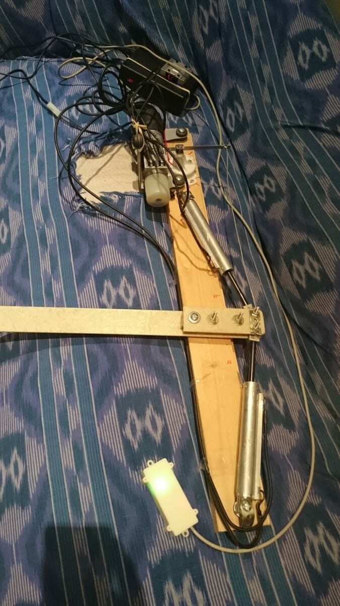
The way I have ‘designed’ it is that up and down keys go up and down by 10 units. The autopilot has 3 control modes compass, GPS (COG shown) and Rudder. The method is chosen by the phone app by virtue of the last setting configured. This is reflected on the watch as the figure top right, the wanted direction. The large figure is the actual measured value. So that would be rudder position or bearing of some form. The text top left is the controller chosen. The number in the outer circle is the speed over ground. I have changed the font since this picture to try to get 3 digits in. The pebble really just acts as a remote control for the phone. There is another neat trick I should do something with. It is a good MOB alarm. All tied in I can turn to wind if the watch gets disconnected from the phone. I just don’t know where the wind is yet…
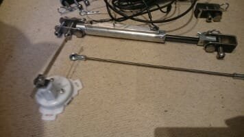
Fairey MaryParticipant Ok, so I have actually been doing something.
I can’t just turn up to the boat and hope it works so I have created a test set up. It is made from an old batten. The pivot point is the left most bolt, I left the length to the left of that to see the speed of movement I would expect from the actual rudder.
From the top; The black box you can see at the top is the project box that contains the arduino and freeboard circuit boards as well as the bluetooth module. You can just make out a red dot which is a 4 digit 7 segment display which I initially used to indicate direction. The metal bit on the top is the motor controller heat sync.
Then coming down you can see the motor and to the right of that the rudder position sensor. There is a bit of fencing wire between that and the end of the ’tiller’.
This is now stand alone and powered by a 12volt car battery I have under my desk.
The cool thing is that I can set the rudder position and it moves to that position.
The difficulties I have between now and a usable system is the quality of the compass which I hope just needs calibrating properly. Unfortunately I have an iron girder near my desk 😉
The other thing that I see as a risky area is the control loop for that includes the compass. I can use the COG from a GPS I have, this de-risks the use of the compass. But it is the tuning of the feedback loop might phase with the motion of the boat if it isn’t tuned properly.
I am using a basic Phase, Integral and Derivitive (PID) loop which I might have to tune based on wave size. I am not sure…
The thing that has made this quite cool is that I have managed to use a bluetooth low energy link to my mobile to do the configuration. The only problem is that I spend too much time making it ‘pretty’ and not enough making it functional. I am learning a lot so sometimes it is more ‘look what I can do’ as opposed to what I need to do.
I hope nobody minds as I have lifted the background image from the Atalanta brochure. The centre of the compass is also an edit from the line drawing.
The idea is that the outer compass is driven by the phones compass so it always points north. The image for the boat rotates within that pointing to its compass bearing. So the image should be aligned with the boat.
The bottom of the screen is, at the moment, three swappable panels for bearing, rudder and GPS speed (obviously, that is important). In the one pictured the smaller number is an editable field which gives the rudder position wanted. The big one is the actual position. I edit the little one and the big one aims at that number. For the rudder it works.
The trick I want to pull off before September is to have the steer by compass bit working. But I don’t have that many weekends left.
But it is looking all very plausible at the moment..
Fairey MaryParticipantUnfortunately this year I am mostly refitting my bank balance. Meaning I would be lucky if I get a good two week break. Which I plan for August.
I have, hopefully not a self delusional, hope that the marina will give Mary a coat of paint over our winter. But I am not sure if I exude sufficient ignorance or wealth to be put at the head of the queue. After all they have seen me take cold showers for a week in March because I am too tight to pay for a B&B.
Other than that it is the Cambridge beer festival this week… http://www.cambridgebeerfestival.com/ . There is also the 3 rivers race on the Norfolk broads http://www.threeriversrace.org.uk at the end of the month. It is not all drizzle and 10 hours a day behind a keyboard 😉
Fairey MaryParticipantSo I have been mostly doing calculations and connecting up the motor drivers. This weekend I build a test rig so I can calculate lock to lock speed. The rams have about 130mm travel which I think will take about 8 seconds flat out. I think there is enough leverage which I can halve and double the speed by only using one ram, but I like the symmetry.
 Thanks to some good drawings done when the twin rudders were done I can get a good idea of how things are going to lay out. From this I can see where the rams would go, I hope that I can work around the exhaust.
I am now fully battling with the feedback loops and am reasonably comfortable that all the kit works. I have plotted the lock to lock speed against the value I request from the motor driver which gives me somewhere between 8 and 20 seconds, the longer is quieter. This is basically flat out in reverse to flat out forwards. I have a hunch most of the feedback loop is correcting against a fixed sample period….. Anyway off to see the boat this week so will forget the technical stuff and get the paint brush out…Fairey MaryParticipantI should rename this blog, “If you want a job done efficiently give it to a lazy person. You would be surprised how much effort they will put in to avoid working”.
Anyway, I hope somebody out their is finding this interesting…I have got as far as getting all the bits together and I have started looking at the software involved. I have stood on the shoulders of giants and created an NMEA database. My aim is now to create functions that populate this as well as using the sensors that generate this data, such as the GPS. For example I will generate rudder position data and add this to the database.The issue I am now finding is that the rudder control is not a simple correction loop. Too far to the right, turn left a bit.. This gets complicated.. There is this thing called a PID but that works for a more linear correction like motor speed. But then I found out about the microtransat and the world started looking a whole lot more interesting. A competition to sail an autonomous 4 metre boat across the Atlantic, the minitransat is 6.5 metres and that carries a person. But back to facilitating my laziness, a lot of the microtransat teams have released their software. This helps…. I hope.
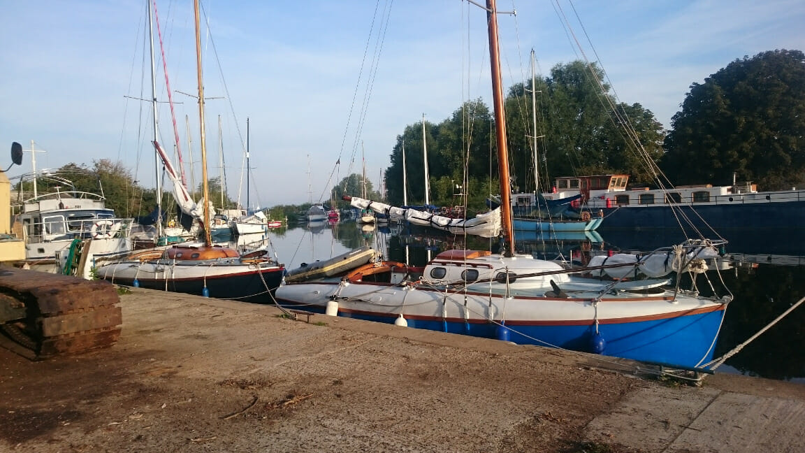
Fairey MaryParticipantAfter much head scratching I have opted for a simpler solution than the SAAB. The BMW mini convertible has a simple two ram solution without solenoids. Simply the motor goes one way the rams go out, reverse the connections and they retract. This arrived as a complete unit with the rams attached so I can see them working. This does not solve the clutch problem but I guess a bypass valve can be gained at a later stage. For now I can focus on the relationship between the compass and the rudder. By swapping the connections on one ram it will retract whilst the other expands. You can see from this picture of Mary that I can attach one ram to each rudder (having two). I should be able to hide the motor and other electronics out of earshot.
 I have most of the electronics now, it is arduino based and I have to admit it is not as effortless as I would have wished. Certain libraries have been compiled with certain versions of the arduino tools and need rework to work with later versions. I am arguing with the GPS at the moment.
The shopping list so far is something like;
Arduino Due £40
Freeboard £70
Potentiometer £15
ArduIMU £50 ( this is the compass and other movement sensors, have a look on youtube )
EM406A GPS £20
Mini Hydraulic motor with Rams £130
Looking at it that way does look like a fools errand. Particularly when you consider that I will need to implement a bypass valve. I also have risks, the rams might not be fast enough… But I have tested most bits in isolation and think it is looking OK.
Fairey MaryParticipantI believe it only has one. It is by no means as crew friendly. There is no rear cabin.
Fairey MaryParticipantPut me down for two copies. Not having Mary featured will teach me for working too hard and not playing, or at least writing an article, this year 😉
- AuthorReplies
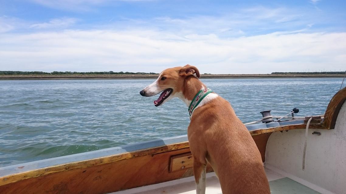 Has your dog got competent crew? Do you think it can teach mine some boat handling skills. I would be happy with the ability to tack, or even take a line when needed.